About Optical cartridge
The Basic principle of the optical cartridge
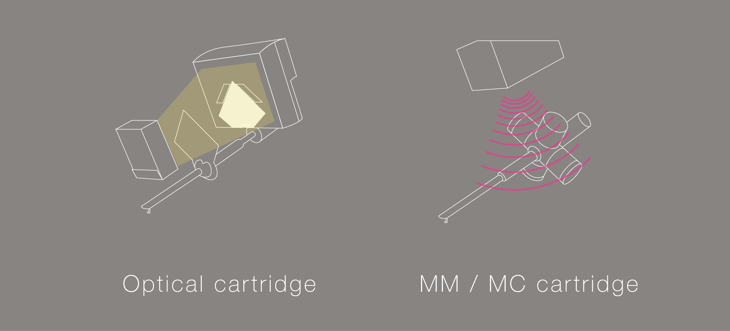
First, We will explain the difference of detection principle between the optical cartridge and MM / MC cartridge.
Both the MM / MC cartridge and the optical cartridge read the record groove through the needle, but the usual MM / MC cartridge detects the music signal by vibrating the magnet (or coil) in the magnetic field.
On the other hand, optical cartridges detect music signals by capturing shadow changes (brightness changes) using LEDs and PD (photo cells).
Because MM / MC cartridges generate electricity by cutting off the magnetic field, magnetic resistance always occurs when the magnet (or coil) moves.
However, the optical cartridge detects only the change in brightness (shadow movement), so no magnetic resistance is generated when the vibration system moves.
Since there is no magnetic resistance applied to the vibration system, the tip of the needle can move smoothly.
This is the primary advantage of optical cartridge technology.
To detect music signals, the MM / MC cartridge must move the magnet or the core and the coil. However, in the case of optical cartridges, it is only necessary to move a light shading plate with a thickness of only 100 microns, so the moving mass is very low.
This is an additional advantage of optical cartridge technology
| MM/MC cartridge | Optical cartridge | |
| Magnetic Resistance | Yes | No |
| Moving Mass | Heavy | Light |
What is the detection principle of the optical cartridge?
We will explain the detection principle of the optical cartridge in more detail.
The optical cartridge detects movement of the needle using infrared LED, light shielding plate and two PD (photo cells).
The operating principle is simple, the shading plate vibrates in front of the LED, and the PD (photo cells) behind it detects the change in brightness.
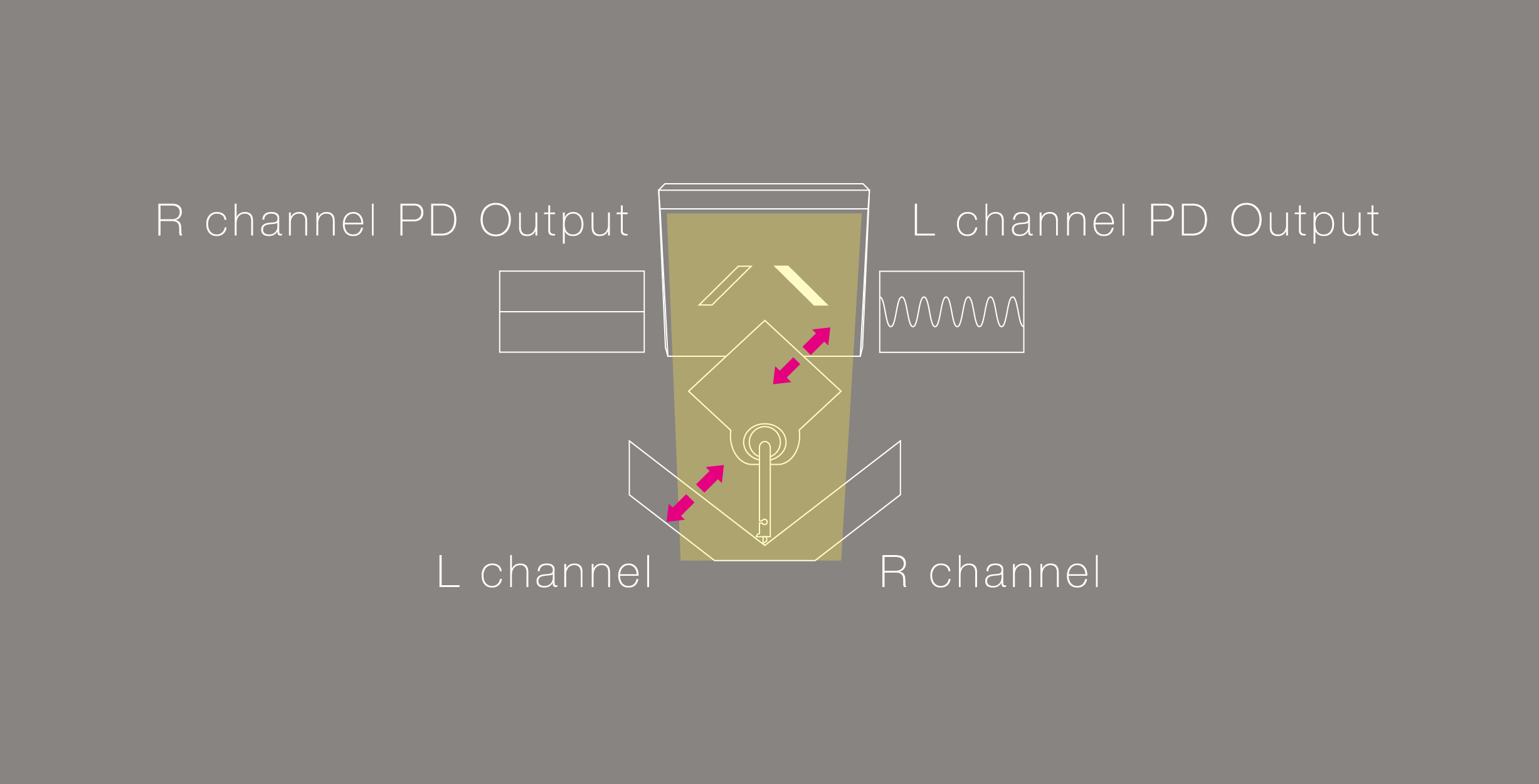
We will explain how to independently detect L and R channel signals from one shading plate.
The above diagram is a view of the light shielding plate and the photo cells from the position where the LED is located.
When the groove of the record vibrates (oblique 45 degrees), the vibration is transmitted from the tip of the needle to the cantilever, and the shading plate also vibrates together.
Since the shading plate vibrates in such a way as to block the light of the front LED, the brightness entering PD (photo cells) changes continuously from bright → dark → bright → dark.
As the photo cells detect changes in brightness created by record groove movement, the output voltage changes accordingly
The movement of the shielding plate will be read as 2 separate stereo channels, by 2 independent photo detectors.
The angular movement of the shielding plate ensures that each photo detector can only pick up information from its corresponding channel. Information from the parallel movement of the opposite channel will not be read, ensuring accurate channel balance and channel separation.
※Since the brightness of the photo cell does not change because the motion of the light shielding plate becomes a parallel movement on the side of the reverse PD (photo cells) side, it is possible to detect audio signals of the left and right channels with one light shielding plate.
This basic detection principle is exactly the same as the photoelectric cartridge 40 years ago.
The important point here is that the output of the PD (photo cell) is the Pure analog sound because the movement of the shading plate = the motion of the record board is output as a voltage change. It is NOT Digital Sound.
| MM/MC cartridge | Optical cartridge | |
| Output | Analog | Analog |
The reason why you need a dedicated equalizer
With an optical cartridge, you can not use a phono equalizer for MM / MC, you must use a phono equalizer dedicated to the DS Audio optical cartridge.
There are two reasons for this
① Voltage is required in order to power the internal LED inside the cartridge, and this voltage is supplied by the equalizer
Power is supplied to the LEDs of the optical cartridge using the tone arm ground (blue and green lines).
For that reason, in order to use the optical cartridge, it is essential that the four cables of the tone arm are properly independent.
(There is no problem with most arms that are currently on the market.)
② The standard RIAA equalization curve required for MM/MC is completely different from equalization required for optical cartridges.
Because the output of an MM / MC cartridge is proportional to its speed, the output increases as the speed rises (= higher frequency). However, the optical cartridge has an amplitude proportional output that outputs flat from the low frequency to the high frequency (same as the old crystal type and capacitor type).
Since the optical cartridge is classified as amplitude proportional and is not affected by changes in speed, even on the same record, it has totally different output properties. Much less EQ correction is required for the amplitude proportional output compared to traditional MM / MC. Because of this, the RIAA correction circuit of the optical cartridge requires much less manipulation of the signal compared to a speed proportional type MM / MC cartridge.
The RIAA correction circuit of the optical cartridge becomes an overwhelmingly simple circuit.
This is yet another advantage of optical cartridge technology
The amplitude proportional type optical cartridge can output the movement of the groove flat from the low frequency to the high frequency, so the RIAA correction circuit of the optical cartridge becomes an overwhelmingly simple circuit compared to the RIAA correction circuit of the speed proportional type.
The RIAA correction circuit of the optical cartridge becomes an overwhelmingly simple circuit.
This is also big merit of the optical cartridge.
Improvements over older optical designs
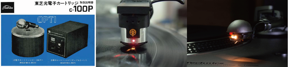
As you probably know, some photoelectric cartridges have been commercialized from Toshiba, Sharp, Trio, Kenwood etc over 40 years ago.
The reason why the optical cartridge once commercialized disappeared is that in the 1970s, it is the biggest factor that the development resources of major companies have shifted from analog to CD.
In addition to that, there was one problem that could not be overcome in the past optical cartridges by any means.
That is a problem of “Heat”.
Forty years ago, LED technology was not well developed, and the only light source available for an optical cartridge was a standard style bulb. These bulbs generated a large amount of heat, which warmed the damper rubber of the cartridge, softening it over time and changing the compliance characteristics. Each company took various measures to overcome this issue, but optical cartridges disappeared from the market before a fundamental solution could be found. Even with this drawback, the sheer quality of the sound of optical cartridges gave the technology a legendary status for over 40 years.
Optical cartridge 40 years ago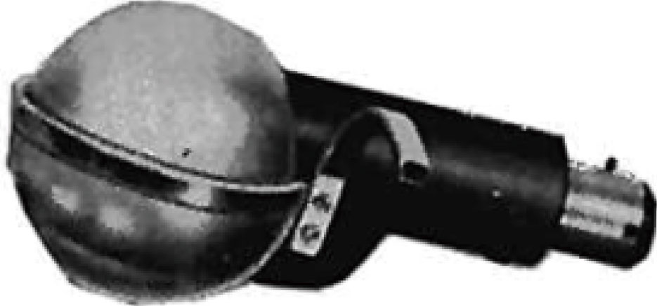 |
DS Audio Optical cartridge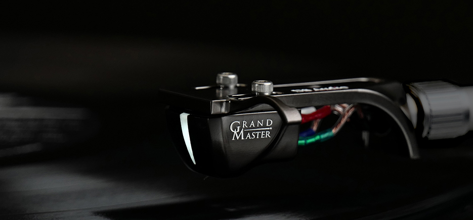 |
|
| Light Source | Lamp | LED |
| Light Receiving Element | Phototransistor | Photodiodes with matching sensitivity characteristics |